

Roland.O
Roland the Mechanic
This diagram is necessary for circuit tracing, power and ground verificatoin and high voltage signal analysis for the direct injection circuits(f3 to f6). It provides pin configurations and module paths needed to scope cylinder specific control pulses and check the integrity of the lines between the injectors and the ECM. Attempting to resolve a direct injection circuit misfire without factory procedures poses safety and equipment risks. The systems operate under high voltage and can easily destroy testing equipment and shock you. Other risks include damage to the ECM and programming faults.
Common questions that this diagram answers
- What is the pinout chart for the No. 1 direct fuel injector f3 connector on a Toyota Harrier ASU60/ASU65?
- How do I check for high-voltage pulse commands at the cylinder 4 injector f6 on an ASU60/ASU65?
- What are the factory wire colours for the direct fuel injector harness on a Toyota Harrier 8AR-FTS engine?
How to access the diagram
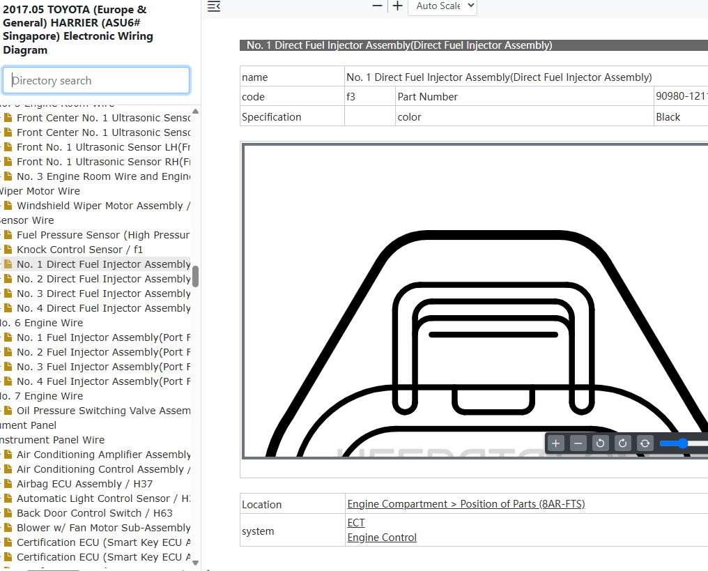
Click on the link below to access the complete OEM Manual, within it you will find the Direct Fuel Injector Wiring Diagram. I have given the screenshot below to help you quickly navigate to the section where the diagram is located. Once you find it, you can then print or save it. Let me know if you face any challenges or have any questions and I will be happy to answer in the thread below. Please note that the year in the document is not the YOM but the document release date so it covers the entire model range. Also note the document applies to all countries where the model is sold Including Singapore, Australia, Malaysia, Kenya, UK, New Zealand, etc.- Access to the OEM Manual
-
View Full Manual on YokaData
The complete manual is hosted by YokaData, the official providers of JDM Repair Data. Click below to open the official, secure vehicle page and view subscription options.
Open Official Manual Page →You will be redirected safely to the secure, official YokaData.com portal.