

Roland.O
Roland the Mechanic
If you are troubleshooting and repairing ABS problems on the Harrier ASU60/ASU65, then this Diagram is crucial as attempting to resolve faults without the OEM layout can lead to incorrect wheel speed readings or accidental terminal damage. This diagram details the ABS architecture, which enables you to undertake power and ground verification, wheel speed sensor circuit tracing and brake actuator module pinout identification. The diagram helps you to perform accurate network analysis on critical data lines which are linked to the VSC systems.
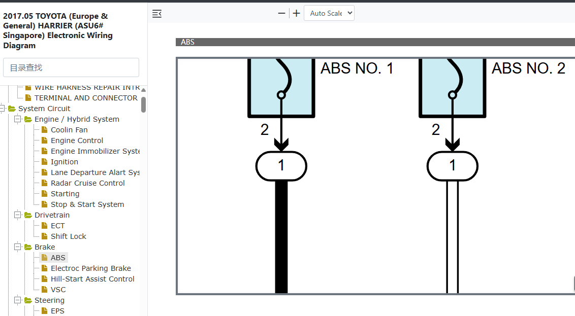
This gives you explicit OEM wire color codes, connection paths and pinouts. See the link below on where to access the diagram. It's part of the complete manual and I have provided the screenshot below on the exact section where to find this diagram.
This gives you explicit OEM wire color codes, connection paths and pinouts. See the link below on where to access the diagram. It's part of the complete manual and I have provided the screenshot below on the exact section where to find this diagram.
- Access to the OEM Manual
-
Access the Verified OEM Manual
To access the full OEM Manual, click on the link below.
Access Manual — $39