

Roland.O
Roland the Mechanic
When working on the Harrier ASU60/65 automatic climate control system, be extra careful as any small wiring misidentification can easily damage the climate control ECU or the sensitive cabin sensors. The factory diagram is critical as it gives you access to circuit paths, component locations and pinout arrangements for the climate control system. It gives you the specific electrical map needed to trace faults, test sensor lines and confidently repair complex A/C or compressor issues.
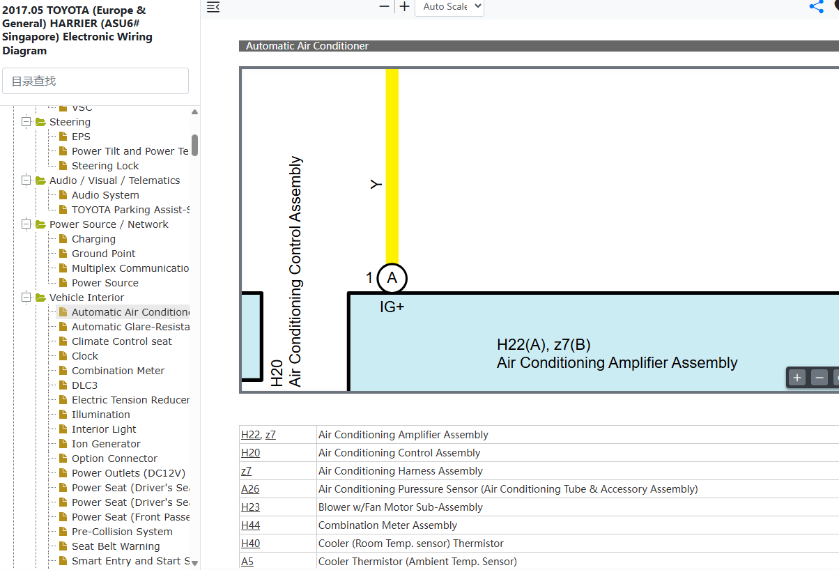
This diagram helps answer these questions
- Where is the automatic climate control ECU located on a Toyota Harrier ASU60/ASU65?
- How do I troubleshoot the blower motor circuit on a Toyota Harrier ASU60/ASU65?
- What is the pinout for the compressor control valve on a Toyota Harrier ASU60/ASU65 automatic A/C system?
- How do I test the cabin temperature sensor wiring on a Toyota Harrier ASU60/ASU65?
How to Access the Diagram
Click on the link below to access the complete OEM Manual, within it you will find the Automatic A/C Wiring Diagram. I have given the screenshot below to help you quickly navigate to the section where the diagram is located. Once you find it, you can then print or save it. Let me know if you face any challenges or have any questions and I will be happy to answer in the thread below. Please note that the year in the document is not the YOM but the document release date so it covers the entire model range. Also note the document applies to all countries where the model is sold Including Singapore, Australia, Malaysia, Kenya, UK, New Zealand, etc.- Access to the OEM Manual
-
Access the Verified OEM Manual
To access the full OEM Manual, click on the link below.
Access Manual — $39