

Roland.O
Roland the Mechanic
This OEM diagram gives you full access to the Harrier ASU60/ASU65 multiplex communication pathways, module nodes and splicing junctions. It gives you the exact technical map needed to trace data high/low lines, test bus resistance and pinpoint which module or circuit is disrupting network communication. Without it, you face a high risk of incorrect circuit identification, incorrect testing and widespread network failure.
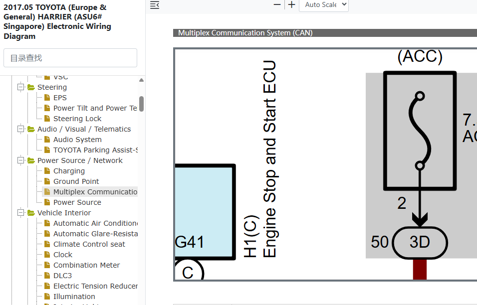
This CAN Network Diagram helps to answer the following questions
- How to diagnose a CAN bus communication failure on a Toyota Harrier ASU60/ASU65?
- Where are the CAN network junction connectors located in a Toyota Harrier ASU60/ASU65?
- What are the resistance specifications for the Toyota Harrier ASU60/ASU65 multiplex communication system?
- Which control modules are on the high-speed CAN bus of a Toyota Harrier ASU60/ASU65?
How to Access the Diagram
Click on the link below to access the complete OEM wiring manual. The screenshot below will help you to nagivate to the exact section where this diagram is. Let me know if you face any challenges or have any questions and I will be happy to answer in the thread below. Please note the year in the document is not the YOM but the document release date, and the model code applies to all countries besides Singapore.- Access to the OEM Manual
-
Access the Verified OEM Manual
To access the full OEM Manual, click on the link below.
Access Manual — $39