

Roland.O
Roland the Mechanic
This OEM combination meter wiring diagram gives you complete circuit layouts, wire colours and exact pinout assignments for the instrument display panel. It gives the specific technical roadmap needed to verify power sources, test data links and resolve gauge, backlighting and warning-light failures. Without this diagram, you risk incorrect wire identification which can cause permanent damage to the sensitive internal circuit board or disrupt the data networks. This diagram gives you the direct factory diagnostic workflow which helps to avoid blind probing.
Common questions that this diagram answers
- What is the pinout diagram for the Toyota Harrier ASU60/ASU65 combination meter connector?
- How do I troubleshoot a blank instrument cluster display on a Toyota Harrier ASU60/ASU65 ?
- Where does the combination meter get its primary power and ground feeds on a Toyota Harrier ASU60/ASU65 ?
- Which CAN bus lines connect directly to the Toyota Harrier ASU60/ASU65 combination meter cluster?
How to access the diagram
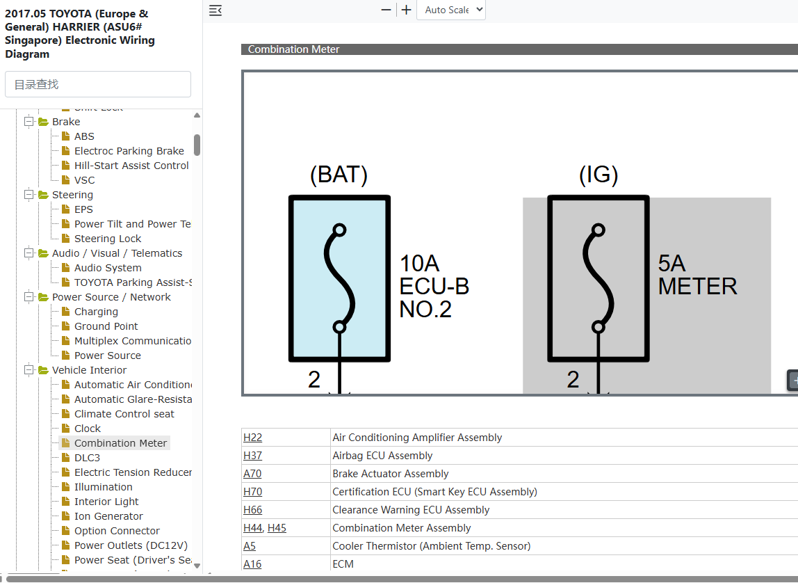
Click on the link below to access the complete OEM Manual, within it you will find the Combination Meter Wiring Diagram. I have given the screenshot below to help you quickly navigate to the section where the diagram is located. Once you find it, you can then print or save it. Let me know if you face any challenges or have any questions and I will be happy to answer in the thread below. Please note that the year in the document is not the YOM but the document release date so it covers the entire model range. Also note the document applies to all countries where the model is sold Including Singapore, Australia, Malaysia, Kenya, UK, New Zealand, etc.- Access to the OEM Manual
-
Access the Verified OEM Manual
To access the full OEM Manual, click on the link below.
Access Manual — $39
Last edited: