

Roland.O
Roland the Mechanic
This document is critical when undertaking power and ground verification, circuit tracing and network communication analysis at the Data Link Connector(OBD2 port). It provides the definitive terminal pinout mapping necessary to test battery voltage, chassis ground, signal ground and multiplex comm lines(CAN High and CAN Low) Attempting to back probe the DLC3 connector without the factory specs poses a high risk of shorting live power circuits and permanently damaging the ECU.
Common questions answered by this document
- What is the OBD2 DLC3 connector pinout for a Toyota Harrier ASU60 / ASU65?
- Why is my scan tool not getting power or communicating with a Toyota Harrier ASU60 / ASU65?
- Which pins on the Toyota Harrier DLC3 connector are used for CAN bus communication testing?
- How do I check for proper ground and power feeds at the Toyota Harrier DLC3 diagnostic port?
How to access the diagram
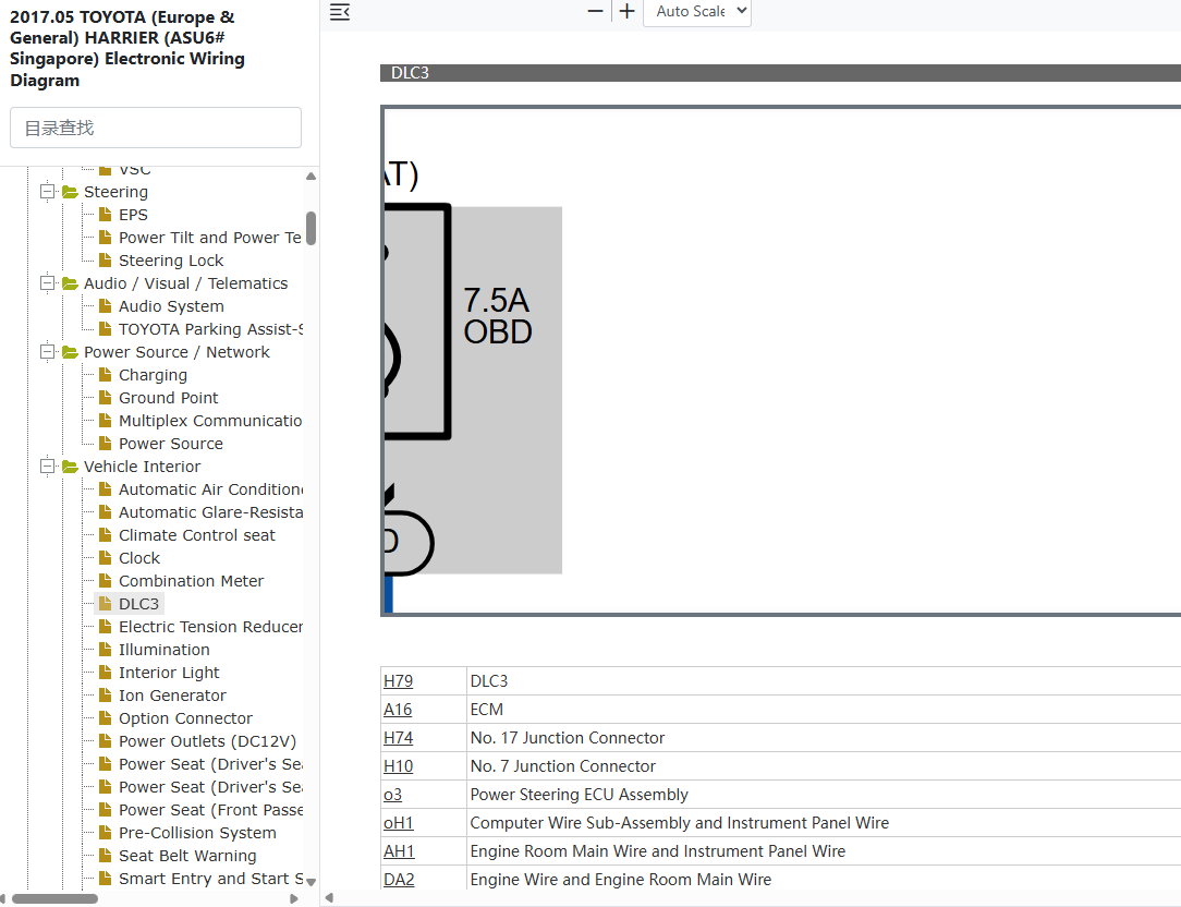
Click on the link below to access the complete OEM Manual, within it you will find the DLC3 Connector Pinout. I have given the screenshot below to help you quickly navigate to the section where the diagram is located. Once you find it, you can then print or save it. Let me know if you face any challenges or have any questions and I will be happy to answer in the thread below. Please note that the year in the document is not the YOM but the document release date so it covers the entire model range. Also note the document applies to all countries where the model is sold Including Singapore, Australia, Malaysia, Kenya, UK, New Zealand, etc.- Access to the OEM Manual
-
Access the Verified OEM Manual
To access the full OEM Manual, click on the link below.
Access Manual — $39