

Roland.O
Roland the Mechanic
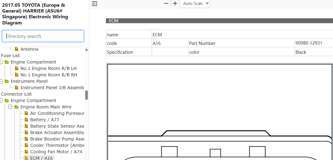
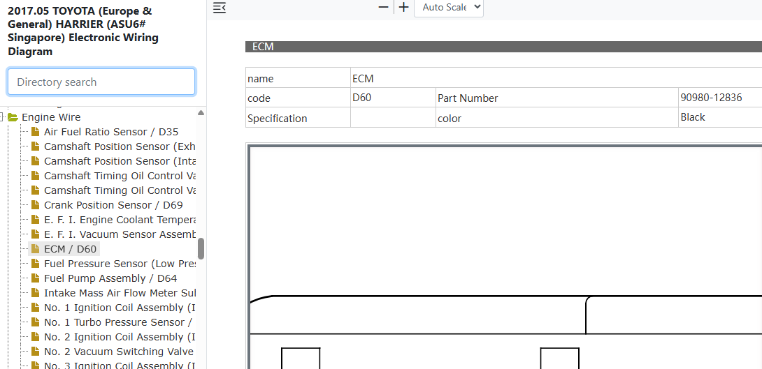
This factory ECM connector pinout chart gives the terminal assignments, voltage thresholds and cuircuit functions for A16 and D60 plugs. It gives the precise steps needed to trace broken engine sensor wires, test critical grounds and isolate hardware faults. Attempting to probe the complex ECM connectors without the OEM pin assignment chart is highly risky and you can short live power feeds and ruin sensitive logic circuits. This can also cause permanent ECM damage and programming failures.
Common questions that this diagram answers
- What is the pinout chart for the Toyota Harrier ASU60/ASU65 ECM A16 connector?
- How do I test engine control module power and ground circuits on a Toyota Harrier ASU60/ASU65?
- Which terminal on the Toyota Harrier ASU60/ASU65 D60 ECM connector controls the main relay signal?
- What are the voltage specifications for sensor reference pins on a Toyota Harrier 8AR-FTS ECM?
How to access the diagram
Click on the link below to access the complete OEM Manual, within it you will find the ECM Connector Pinout. I have given the screenshot below to help you quickly navigate to the section where the diagram is located. Once you find it, you can then print or save it. Let me know if you face any challenges or have any questions and I will be happy to answer in the thread below. Please note that the year in the document is not the YOM but the document release date so it covers the entire model range. Also note the document applies to all countries where the model is sold Including Singapore, Australia, Malaysia, Kenya, UK, New Zealand, etc.- Access to the OEM Manual
-
View Full Manual on YokaData
The complete manual is hosted by YokaData, the official providers of JDM Repair Data. Click below to open the official, secure vehicle page and view subscription options.
Open Official Manual Page →You will be redirected safely to the secure, official YokaData.com portal.