

Roland.O
Roland the Mechanic
This diagram gives you complete circuit tracks, wire colour codes and connector pinouts for the f2 plug assembly. It gives the OEM procedures needed to check for sensor supply drops, test grounding tracks and isolate electrical line faults from actual fuel pressure degradation. Without this diagram you can easily misdiagnose and cause damage to the expensive ECM and sensitive data bus.
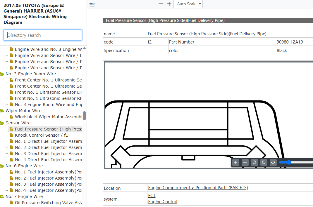
Common questions that this diagram answers
- What is the pinout chart for the high-pressure fuel sensor f2 connector on a Toyota Harrier ASU60/ASU65?
- How do I test the 5V reference voltage at the high-pressure fuel rail sensor on a Toyota Harrier ASU60/ASU65?
- What are the wire colours for the high-side fuel pressure sensor on a Toyota Harrier 8AR-FTS engine?
- How do you isolate an electrical harness fault from a failing fuel pressure sensor when diagnosing direct-injection rail pressure codes for Harrier ASU60/ASU65?