

Roland.O
Roland the Mechanic
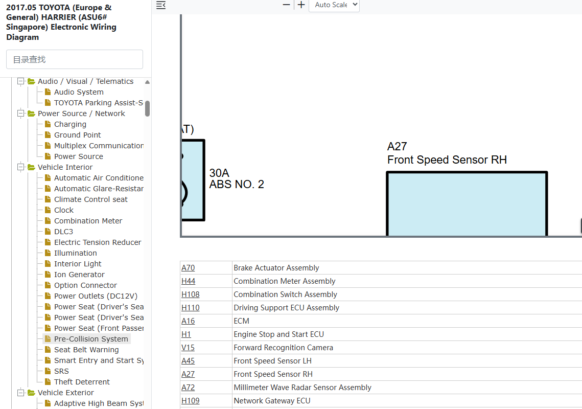
This is an essential diagram for network communication analysis, circuit tracing and power/ground verification across safety critical components. It gives the precise connections linking the forward recognition camera, millimeter-wave radar sensor and driving support ECUs which allows for exact pinout verification of power feeds and data lines. Attempting to fix the system without the OEM schematics can cause permanent programming or calibration errors within the vehicle's advanced driver-assistance network.
Common questions that this diagram answers
- Where is the Pre-Collision System radar sensor located on a Toyota Harrier ASU60/ASU65?
- How do I troubleshoot a CAN bus communication fault in the Toyota Harrier PCS network?
- What is the pinout configuration for the forward recognition camera on a Toyota Harrier ASU60/ASU65?