

Roland.O
Roland the Mechanic
If you are working on the adaptive cruise control on the Harrier ASU60/65, this schematic provides exact wiring configurations that will enable you to undertake power and ground verification, radar sensor circuit tracing and bus communication analysis. It is necessary for identifying electrical dropouts between the radar sensor unit, the braking system and the primary powertrain modules. It gives you the specific pinouts, network terminal points and factory wire shielding data needed to isolate complex ADAS electrical faults. It provides you with the exact layout required to trace sensor supply lines and verify network communication paths so you can confidently restore active driver assistance features.
Without this diagram, you will be groping in the dark and can easily trigger calibration faults and communication network disruptions. Below is the link to where you can access the OEM repair diagram as well as the entire repair database for the Harrier ASU60/65. The screenshot below is from the actual database. FYI: The year on the document is the document release date and not the YOM.
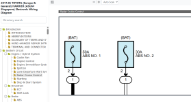
Without this diagram, you will be groping in the dark and can easily trigger calibration faults and communication network disruptions. Below is the link to where you can access the OEM repair diagram as well as the entire repair database for the Harrier ASU60/65. The screenshot below is from the actual database. FYI: The year on the document is the document release date and not the YOM.